Rp.Discontinue
Introduction.
Hook your Arduino up to GSM/GPRS cell phone network with GPRS shield! You can use your Arduino to dial a phone number or send a text to your friend via easy to use AT commands now. This new version features a quad-band low power consumption GSM/GPRS module SIM900 as well as a compact PCB antenna. Meanwhile, improvements on interfaces and basic circuit have been taken to make it more concise and reliable. Check out
the improvement details of V2.0.
Model:SLD01098P
Features
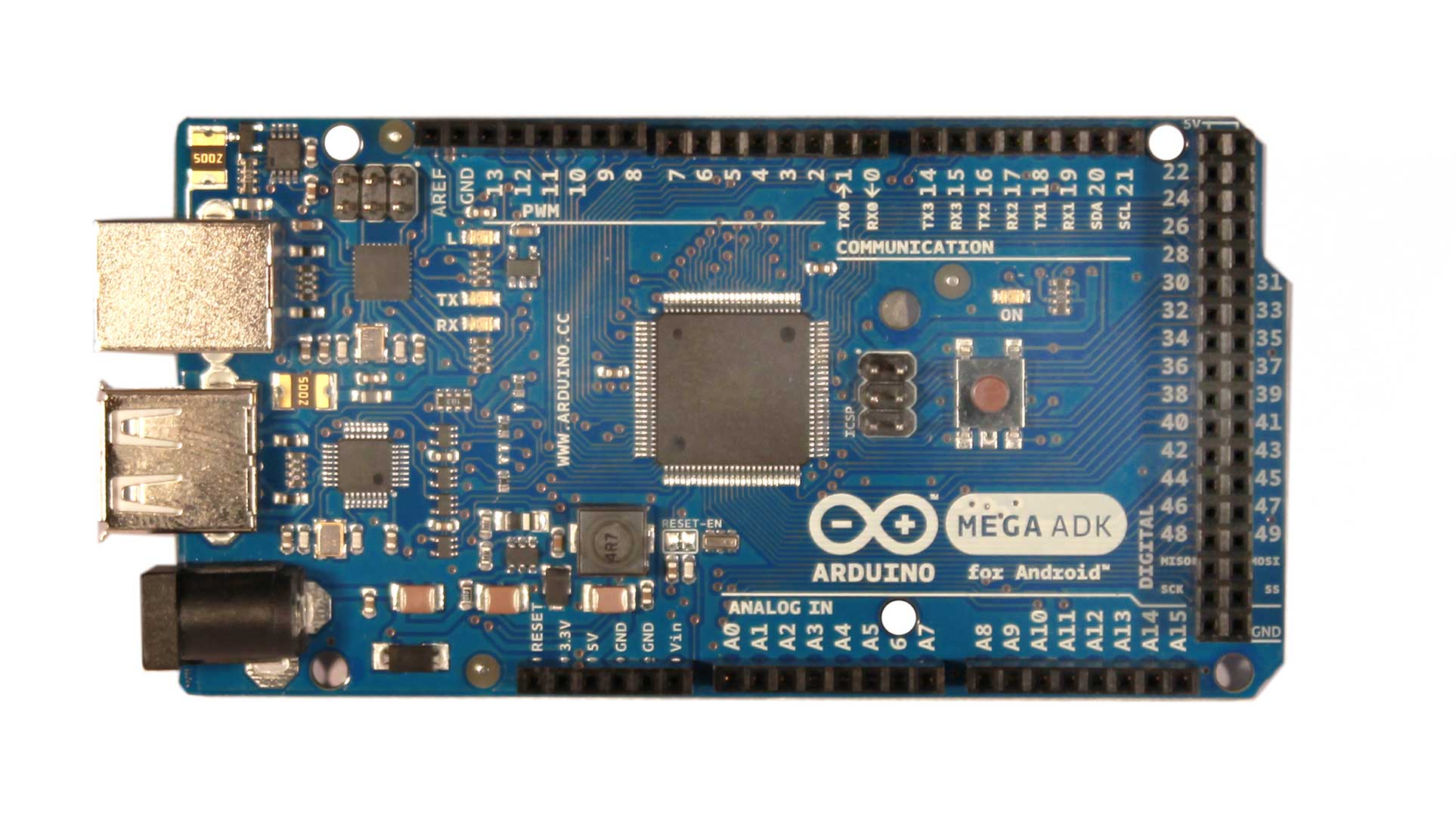
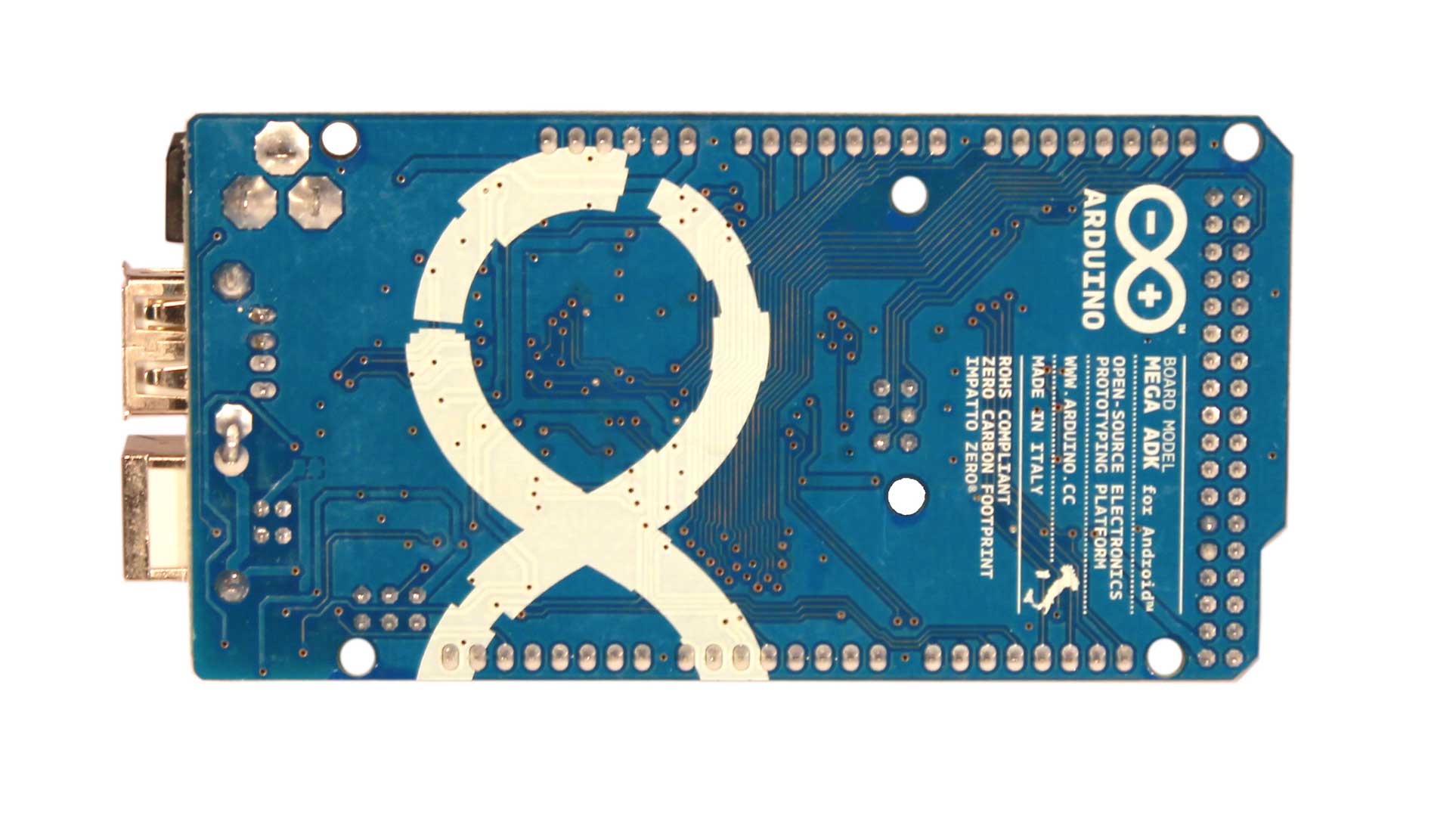
- Compatible with standard Arduino and Arduino Mega
- Selectable interface between hardware serial port and software serial port
- Quad band support: 850/900/1800/1900MHz
- Support TCP/UDP protocols
- Full control via AT commands set: Standard - GSM 07.07 & 07.05 and Enhanced - SIMCOM AT Commands
- 2-in-1 headset jack
- Convenient external SIM card holder
- Low power consumption: 1.5mA(sleep mode)
- 3V CR1220 Battery Holder Connetor
Cautions
- Make sure your SIM card is unlocked.
- GPRS Shield doesn't come with ESD precautions. Take special care when handling it in dry weather.
- The factory default setting for the GPRS Shield UART is 19200 bps 8-N-1. (Can be changed using AT commands).
Interface Function

Antenna interface: external antenna could be added here for expansion
Serial port select: select either software serial port or hardware serial port as interface with Arduino
Hardware Serial: D0 and D1 of Arduino/Seeeduino
Software serial: D7 and D8 of Arduino/Seeeduino only
Status indicator: tell whether SIM900 is on
Power-on indicator: tell whether the GPRS Shield is on
Net indicator: tell the status about SIM900 linking to the net
GPIO,PWM and ADC of SIM900: GPIO,PWM and ADC pins breakout of SIM900
Headsets interface: mic and earphone 2-in-1 interface
Power button: turn on or off SIM900
Pins usage on Arduino
D0: Used as RX of hardware serial port
D1: Used as TX of hardware serial port
D7: Used as RX of software serial port
D8: Used as TX of software serial port
D9: Used as software power button for SIM900
VIN: Used if you select external 6.5V~12Vpower supply for the Arduino and GPRS Shield
LED Status Description
| LED
|
Status
|
Function
|
| Power-on indicator(Green)
|
Off
|
Power of GPRS Shield is off
|
|
On
|
Power of GPRS Shield is on
|
| Status Indicator(Red)
|
Off
|
Power off
|
|
On
|
Power on
|
| Net indicator(Green)
|
Off
|
SIM900 is not working
|
|
64ms On/800ms Off
|
SIM900 does not find the network
|
|
64ms On/3000ms Off
|
SIM900 finds the network
|
|
64ms On/300ms Off
|
GPRS communication
|
Usage
As you receive the GPRS Shield, what would be the first thing you want to do with it? Send out a text (SMS)? Or call up someone (headset required)? You can do all of this by talking to the GPRS Shield using AT Commands - a special language that it understands.
AT Commands are simple textual commands sent to the GPRS modem over its serial interface (UART), so you can use any serial terminal software to communicate with it.
Hardware Installation
Follow the steps below to set up the hardware system.
1. Insert an unlocked SIM card to SIM Card Holder
A 6 Pin Holder for SIM Cards. Both 1.8 volts and 3.0 volts SIM Cards are supported by SIM900, the SIM card voltage type is automatically detected.

 2. Check the antenna
Make sure the antenna have installed properly in the antenna interface.
 3. Communication port configuration
The GPRS shield can be controlled via hardware serial port or software serial port of Arduino. Here we use the software serial port as default. Choose it by inserting jumper caps as below.
4. Plug to Arduino
Stack the GPRS Shield onto Arduino.
 5. Power up Arduino
Power up Arduino by USB cable or DC Jack. The Power-on indicator LED should light up once connectted.

Fun with AT Commands
Let's have a try to control the GPRS shield with AT commands.
The GPRS Shield comes with all accessories that you need to get started with sending data over the GSM network except an Arduino board and a GSM SIM Card. If you want to make voice calls, you would also require a headset with microphone.
Step 1: Test Setup
1.Create a new Arduino sketch and paste the codes below to it.
//Serial Relay - Arduino will patch a
//serial link between the computer and the GPRS Shield
//at 19200 bps 8-N-1
//Computer is connected to Hardware UART
//GPRS Shield is connected to the Software UART

#include <SoftwareSerial.h>

SoftwareSerial GPRS(7, 8);
unsigned char buffer[64]; // buffer array for data recieve over serial port
int count=0;     // counter for buffer array
void setup()
{
  GPRS.begin(19200);               // the GPRS baud rate
  Serial.begin(19200);             // the Serial port of Arduino baud rate.

}

void loop()
{
  if (GPRS.available())              // if date is comming from softwareserial port ==> data is comming from gprs shield
  {
    while(GPRS.available())          // reading data into char array
    {
      buffer[count++]=GPRS.read();     // writing data into array
      if(count == 64)break;
  }
    Serial.write(buffer,count);            // if no data transmission ends, write buffer to hardware serial port
    clearBufferArray();              // call clearBufferArray function to clear the storaged data from the array
    count = 0;                       // set counter of while loop to zero


  }
  if (Serial.available())            // if data is available on hardwareserial port ==> data is comming from PC or notebook
    GPRS.write(Serial.read());       // write it to the GPRS shield
}
void clearBufferArray()              // function to clear buffer array
{
  for (int i=0; i<count;i++)
    { buffer[i]=NULL;}                  // clear all index of array with command NULL
}
2. Upload the code to Arduino. If you do not know how to upload the code, please click
here.
3. Download and fire up
serial tool if you don't have one. Choose the correct COM port for Arduino, and set it to operate at 19200 8-N-1 and then click "Open Com". You can also use AT Command Tester to send AT commands. Please click
here if you are interesting in it.
4. Power up the SIM900 by pressing the power button in about 2 seconds. The red LED will be on. The green one beside it will blink. If the shield join the network sucessfully, the green LED will blink every 3 seconds.
5. You should find the message on the serial monitor as below which is sent by the SIM900 to inform you it has joined the network:
RDY

+CFUN: 1

+CPIN: READY

Call Ready
If you can not see the messages in the serial monitor, you should click the "send new" option that will add carriage return at the end of AT command and then send AT command "AT+IPR=19200" to set the baud rate of the SIM900.
 Notice: How AT commands control the GPRS Shield
The ATmega328P microcontroller on Duemilanove board has only one UART which is used for communicating with the PC. What we need is an Arduino Sketch running inside the ATmega328P that would emulate a second serial port (UART) using software on the digital pins D8 and D7 and patch through all the communication between this second software serial port and the actual hardware serial port. By doing this, all the data coming from the computer (connected to the actual hardware UART) would be routed to the GPRS Shield (connected to software UART) then, we would be able to issue AT commands to control the GPRS Shield. The block diagram outlining this scheme is shown below.
 Step 2: Send A Text Message(SMS)
Based on step 1, now we try to send a text message by using AT commands.
- The GPRS Shield can send SMSes in two modes: Text mode and PDU (or binary) mode. To send out a human readable message, select the text mode by sending AT command "AT+CMGF=1". If succeeds, The GPRS Shield will respond with an OK.
- To enter the number of your target phone, tick "SendNew" option and send AT+CMGS="136*****556". This will instruct the GPRS Shield to send a new message to the phone number specified (replace the number with the phone number of your target phone). The GPRS Shield will send a> to remind you of typing the message. Please note that phone number specified as parameter in any AT command must be in E.123 format.
- After entering your message, tick "send hex" option and then send a hex: 1A. The modem will accept the message and respond with an OK. A few moments later, the message should be received on the handset whose number you had specified. I sent "How are you ?". You can check the histroy by clicking "EXT". The commands histroy is listed below "Set Multi Char".

NOTE: If, in spite of following the steps as specified above, you're unable to receive the message on the target handset, you might need to set the SMS Message Center number. Send the following command between the AT+CMGF and AT+CMGS commands:AT+CSCA="+919032055002". Replace the phone number specified with the SMS Center number of your GSM Service Provider. The message center number is specific to each service provider. You can get the message center number by calling up the customer care center of the GSM Service Provider and asking them for it.
Step 3: Make a telephone call with the AT commands
- Restart the SIM900 if switching from sending texts to making phone calls.
- Replace the phone number with your target number in the command “ATD186*****308;”(without the quotes) and press Enter key to send it out. If it succeds, a message "ATH OK" will show up as the picture below. Otherwise, "No CRRLIER" will show up instead. The reason might be unexistent phone number or incorrect command format.

Step 4: Exploring Further
Now that you have gotten a taste of how the AT Commands work, you can try out some more of them by moving on to developing sketches for Arduino to use the GPRS Shield. This involves creating a sketch to send out a sequence of AT Commands to the GPRS Shield to perform tasks as sending an SMS, making a call or sending data over a GPRS connection. You can go through the
AT Commands reference manual to figure out the sequence of commands required to do a particular task. If while developing an Arduino sketch, you find that the GPRS Shield doesn't execute what you have expected, check the AT Commands you sent to find out whether the spelling or sequence gets wrong. To do this, reload the serial relay sketch attached above in step 1 and type out the AT Commands manually and check the output. The responses sent by the GPRS Shield will help you debug the AT Command sequence.
A Simple Source Code Examples for phone calls and sending text messages
The demo code below is for the Xduino to send SMS message/dial a voice call. It has been tested on Arduino Duemilanove but will work on any compatible variant. Please note that this sketch uses the software UART of ATmega328P. So follow the steps below for running this sketch.
1. Follow the hardware installation steps to set up the hardware system.
2. Create an Arduino project and paste the program below to it. Replace the following items in the code:
-
-
- 1) Phone number. Replace the number “+86186*****308”(+86:China code) with the phone number of the target phone, don't forget add the country code.
- 2) The content of the message. Change the content “How are you ?” to what you want to send.
 /*Note: this code is a demo for how to using GPRS Shield to send SMS message and dial a voice call.

The microcontrollers Digital Pin 7 and hence allow unhindered communication with GPRS Shield using SoftSerial Library.
IDE: Arduino 1.0 or later */


#include <SoftwareSerial.h>
#include <String.h>

SoftwareSerial mySerial(7,8);

void setup()
{
  mySerial.begin(19200);               // the GPRS baud rate
  Serial.begin(19200);    // the GPRS baud rate
  delay(500);
}

void loop()
{
  //after start up the program, you can using terminal to connect the serial of gprs shield,
  //if you input 't' in the terminal, the program will execute SendTextMessage(), it will show how to send a sms message,
  //if input 'd' in the terminal, it will execute DialVoiceCall(), etc.

  if (Serial.available())
    switch(Serial.read())
   {
     case 't':
       SendTextMessage();
       break;
     case 'd':
       DialVoiceCall();
       break;

   }
  if (mySerial.available())
    Serial.write(mySerial.read());
}

///SendTextMessage()
///this function is to send a sms message
void SendTextMessage()
{
  mySerial.print("AT+CMGF=1\r");    //Because we want to send the SMS in text mode
  delay(100);
  mySerial.println("AT + CMGS = \"+86186*****308\"");//send sms message, be careful need to add a country code before the cellphone number
  delay(100);
  mySerial.println("How are you ?");//the content of the message
  delay(100);
  mySerial.println((char)26);//the ASCII code of the ctrl+z is 26
  delay(100);
  mySerial.println();
}

///DialVoiceCall
///this function is to dial a voice call
void DialVoiceCall()
{
  mySerial.println("ATD + +86186*****308;");//dial the number
  delay(100);
  mySerial.println();
}

void ShowSerialData()
{
  while(mySerial.available()!=0)
    Serial.write(mySerial.read());
}
3. Upload the code. If you input't', your GPRS shield will send a SMS message to the target cellphone. If you input'd', the program will dial a call to the target cell phone.
4. If the program returns error in the terminal after you typed the command, don't worry, just try input the command again.
Improvement Details of GPRS Shield V2.0
Appearance Change
1) V2.0 adopts a standard shield outline as well as a protective shell;
2) Duck antenna is replaced by a compact PCB antenna;
3) Mic and earphone interfaces are replaced by 2-in-1 headset jack on V2.0.
Power Circuitry Change
Replace the original LDO circuitry with DC-DC circuitry. Heat dissipation gets lower and efficiency gets higher up to 80%+. Meanwhile, the EXT_PWR jack on V1.0 was removed. V2.0 can draw current directly from Arduino now without additional 5V adapter.

Soft Start Circuitry
Soft start circuitry is added in the new version to smooth out the power shock at the moment the shield turns on, preventing the shield from unexpected reset issue.

Below is how power shock affects the 5V pin of Arduino:

The blue line is the 5V signal from Arduino and the yellow is the power pin of GPRS shield V1.0. The blue line drops significantly down to 1.08V at the moment the GPRS shield turns on, which finally results in a system reset because it outlasts 3ms.
The same process on the new version:

This time the power-on only causes a pulse in small magnitude. No reset turns up because the pulse only lasts about 1us.
Next let's have a look at the startup situation of the soft start circuitry. The red line below represents the wire between the Q5 and D2:

The signal is relativly flat. There are about 2.5s charging time for GPRS shield. In this time scale, there is no noticable shake of the 5V signal of Arduino.
Antenna Revision
The maximum transit power of SIM900 is 30dBm(1w). However the output power of V1.0 is only 0.4W. In this new version, transit power is turned up to 29dBm above(0.8w+), giving you more reliable and firm signal transmission.
Resource
GPRS Shield Eagle File
GPRS Shield V2 Schematic.pdf
SIM900 Datasheeet
AT Commands v1.00 &
AT Commands v1.03 &
Hardware Design - SIM900 Documentation
SIM900 firmware and tool(firmware:1137B08SIM900M64_ST) for firmware upgrade
SIM_900_AGPS_instructionsSIM_900_AGPS_instructions
Rp.Discontinue
Introduction.
Hook your Arduino up to GSM/GPRS cell phone network with GPRS shield! You can use your Arduino to dial a phone number or send a text to your friend via easy to use AT commands now. This new version features a quad-band low power consumption GSM/GPRS module SIM900 as well as a compact PCB antenna. Meanwhile, improvements on interfaces and basic circuit have been taken to make it more concise and reliable. Check out
the improvement details of V2.0.
Model:SLD01098P
Features
- Compatible with standard Arduino and Arduino Mega
- Selectable interface between hardware serial port and software serial port
- Quad band support: 850/900/1800/1900MHz
- Support TCP/UDP protocols
- Full control via AT commands set: Standard - GSM 07.07 & 07.05 and Enhanced - SIMCOM AT Commands
- 2-in-1 headset jack
- Convenient external SIM card holder
- Low power consumption: 1.5mA(sleep mode)
- 3V CR1220 Battery Holder Connetor
Cautions
- Make sure your SIM card is unlocked.
- GPRS Shield doesn't come with ESD precautions. Take special care when handling it in dry weather.
- The factory default setting for the GPRS Shield UART is 19200 bps 8-N-1. (Can be changed using AT commands).
Interface Function
Antenna interface: external antenna could be added here for expansion
Serial port select: select either software serial port or hardware serial port as interface with Arduino
Hardware Serial: D0 and D1 of Arduino/Seeeduino
Software serial: D7 and D8 of Arduino/Seeeduino only
Status indicator: tell whether SIM900 is on
Power-on indicator: tell whether the GPRS Shield is on
Net indicator: tell the status about SIM900 linking to the net
GPIO,PWM and ADC of SIM900: GPIO,PWM and ADC pins breakout of SIM900
Headsets interface: mic and earphone 2-in-1 interface
Power button: turn on or off SIM900
Pins usage on Arduino
D0: Used as RX of hardware serial port
D1: Used as TX of hardware serial port
D7: Used as RX of software serial port
D8: Used as TX of software serial port
D9: Used as software power button for SIM900
VIN: Used if you select external 6.5V~12Vpower supply for the Arduino and GPRS Shield
LED Status Description
| LED
|
Status
|
Function
|
| Power-on indicator(Green)
|
Off
|
Power of GPRS Shield is off
|
|
On
|
Power of GPRS Shield is on
|
| Status Indicator(Red)
|
Off
|
Power off
|
|
On
|
Power on
|
| Net indicator(Green)
|
Off
|
SIM900 is not working
|
|
64ms On/800ms Off
|
SIM900 does not find the network
|
|
64ms On/3000ms Off
|
SIM900 finds the network
|
|
64ms On/300ms Off
|
GPRS communication
|
Usage
As you receive the GPRS Shield, what would be the first thing you want to do with it? Send out a text (SMS)? Or call up someone (headset required)? You can do all of this by talking to the GPRS Shield using AT Commands - a special language that it understands.
AT Commands are simple textual commands sent to the GPRS modem over its serial interface (UART), so you can use any serial terminal software to communicate with it.
Hardware Installation
Follow the steps below to set up the hardware system.
1. Insert an unlocked SIM card to SIM Card Holder
A 6 Pin Holder for SIM Cards. Both 1.8 volts and 3.0 volts SIM Cards are supported by SIM900, the SIM card voltage type is automatically detected.
2. Check the antenna
Make sure the antenna have installed properly in the antenna interface.
3. Communication port configuration
The GPRS shield can be controlled via hardware serial port or software serial port of Arduino. Here we use the software serial port as default. Choose it by inserting jumper caps as below.
4. Plug to Arduino
Stack the GPRS Shield onto Arduino.
5. Power up Arduino
Power up Arduino by USB cable or DC Jack. The Power-on indicator LED should light up once connectted.
Fun with AT Commands
Let's have a try to control the GPRS shield with AT commands.
The GPRS Shield comes with all accessories that you need to get started with sending data over the GSM network except an Arduino board and a GSM SIM Card. If you want to make voice calls, you would also require a headset with microphone.
Step 1: Test Setup
1.Create a new Arduino sketch and paste the codes below to it.
//Serial Relay - Arduino will patch a
//serial link between the computer and the GPRS Shield
//at 19200 bps 8-N-1
//Computer is connected to Hardware UART
//GPRS Shield is connected to the Software UART

#include <SoftwareSerial.h>

SoftwareSerial GPRS(7, 8);
unsigned char buffer[64]; // buffer array for data recieve over serial port
int count=0;     // counter for buffer array
void setup()
{
  GPRS.begin(19200);               // the GPRS baud rate
  Serial.begin(19200);             // the Serial port of Arduino baud rate.

}

void loop()
{
  if (GPRS.available())              // if date is comming from softwareserial port ==> data is comming from gprs shield
  {
    while(GPRS.available())          // reading data into char array
    {
      buffer[count++]=GPRS.read();     // writing data into array
      if(count == 64)break;
  }
    Serial.write(buffer,count);            // if no data transmission ends, write buffer to hardware serial port
    clearBufferArray();              // call clearBufferArray function to clear the storaged data from the array
    count = 0;                       // set counter of while loop to zero


  }
  if (Serial.available())            // if data is available on hardwareserial port ==> data is comming from PC or notebook
    GPRS.write(Serial.read());       // write it to the GPRS shield
}
void clearBufferArray()              // function to clear buffer array
{
  for (int i=0; i<count;i++)
    { buffer[i]=NULL;}                  // clear all index of array with command NULL
}
2. Upload the code to Arduino. If you do not know how to upload the code, please click
here.
3. Download and fire up
serial tool if you don't have one. Choose the correct COM port for Arduino, and set it to operate at 19200 8-N-1 and then click "Open Com". You can also use AT Command Tester to send AT commands. Please click
here if you are interesting in it.
4. Power up the SIM900 by pressing the power button in about 2 seconds. The red LED will be on. The green one beside it will blink. If the shield join the network sucessfully, the green LED will blink every 3 seconds.
5. You should find the message on the serial monitor as below which is sent by the SIM900 to inform you it has joined the network:
RDY

+CFUN: 1

+CPIN: READY

Call Ready
If you can not see the messages in the serial monitor, you should click the "send new" option that will add carriage return at the end of AT command and then send AT command "AT+IPR=19200" to set the baud rate of the SIM900.
Notice: How AT commands control the GPRS Shield
The ATmega328P microcontroller on Duemilanove board has only one UART which is used for communicating with the PC. What we need is an Arduino Sketch running inside the ATmega328P that would emulate a second serial port (UART) using software on the digital pins D8 and D7 and patch through all the communication between this second software serial port and the actual hardware serial port. By doing this, all the data coming from the computer (connected to the actual hardware UART) would be routed to the GPRS Shield (connected to software UART) then, we would be able to issue AT commands to control the GPRS Shield. The block diagram outlining this scheme is shown below.
Step 2: Send A Text Message(SMS)
Based on step 1, now we try to send a text message by using AT commands.
- The GPRS Shield can send SMSes in two modes: Text mode and PDU (or binary) mode. To send out a human readable message, select the text mode by sending AT command "AT+CMGF=1". If succeeds, The GPRS Shield will respond with an OK.
- To enter the number of your target phone, tick "SendNew" option and send AT+CMGS="136*****556". This will instruct the GPRS Shield to send a new message to the phone number specified (replace the number with the phone number of your target phone). The GPRS Shield will send a> to remind you of typing the message. Please note that phone number specified as parameter in any AT command must be in E.123 format.
- After entering your message, tick "send hex" option and then send a hex: 1A. The modem will accept the message and respond with an OK. A few moments later, the message should be received on the handset whose number you had specified. I sent "How are you ?". You can check the histroy by clicking "EXT". The commands histroy is listed below "Set Multi Char".
NOTE: If, in spite of following the steps as specified above, you're unable to receive the message on the target handset, you might need to set the SMS Message Center number. Send the following command between the AT+CMGF and AT+CMGS commands:AT+CSCA="+919032055002". Replace the phone number specified with the SMS Center number of your GSM Service Provider. The message center number is specific to each service provider. You can get the message center number by calling up the customer care center of the GSM Service Provider and asking them for it.
Step 3: Make a telephone call with the AT commands
- Restart the SIM900 if switching from sending texts to making phone calls.
- Replace the phone number with your target number in the command “ATD186*****308;”(without the quotes) and press Enter key to send it out. If it succeds, a message "ATH OK" will show up as the picture below. Otherwise, "No CRRLIER" will show up instead. The reason might be unexistent phone number or incorrect command format.
Step 4: Exploring Further
Now that you have gotten a taste of how the AT Commands work, you can try out some more of them by moving on to developing sketches for Arduino to use the GPRS Shield. This involves creating a sketch to send out a sequence of AT Commands to the GPRS Shield to perform tasks as sending an SMS, making a call or sending data over a GPRS connection. You can go through the
AT Commands reference manual to figure out the sequence of commands required to do a particular task. If while developing an Arduino sketch, you find that the GPRS Shield doesn't execute what you have expected, check the AT Commands you sent to find out whether the spelling or sequence gets wrong. To do this, reload the serial relay sketch attached above in step 1 and type out the AT Commands manually and check the output. The responses sent by the GPRS Shield will help you debug the AT Command sequence.
A Simple Source Code Examples for phone calls and sending text messages
The demo code below is for the Xduino to send SMS message/dial a voice call. It has been tested on Arduino Duemilanove but will work on any compatible variant. Please note that this sketch uses the software UART of ATmega328P. So follow the steps below for running this sketch.
1. Follow the hardware installation steps to set up the hardware system.
2. Create an Arduino project and paste the program below to it. Replace the following items in the code:
-
-
- 1) Phone number. Replace the number “+86186*****308”(+86:China code) with the phone number of the target phone, don't forget add the country code.
- 2) The content of the message. Change the content “How are you ?” to what you want to send.
 /*Note: this code is a demo for how to using GPRS Shield to send SMS message and dial a voice call.

The microcontrollers Digital Pin 7 and hence allow unhindered communication with GPRS Shield using SoftSerial Library.
IDE: Arduino 1.0 or later */


#include <SoftwareSerial.h>
#include <String.h>

SoftwareSerial mySerial(7,8);

void setup()
{
  mySerial.begin(19200);               // the GPRS baud rate
  Serial.begin(19200);    // the GPRS baud rate
  delay(500);
}

void loop()
{
  //after start up the program, you can using terminal to connect the serial of gprs shield,
  //if you input 't' in the terminal, the program will execute SendTextMessage(), it will show how to send a sms message,
  //if input 'd' in the terminal, it will execute DialVoiceCall(), etc.

  if (Serial.available())
    switch(Serial.read())
   {
     case 't':
       SendTextMessage();
       break;
     case 'd':
       DialVoiceCall();
       break;

   }
  if (mySerial.available())
    Serial.write(mySerial.read());
}

///SendTextMessage()
///this function is to send a sms message
void SendTextMessage()
{
  mySerial.print("AT+CMGF=1\r");    //Because we want to send the SMS in text mode
  delay(100);
  mySerial.println("AT + CMGS = \"+86186*****308\"");//send sms message, be careful need to add a country code before the cellphone number
  delay(100);
  mySerial.println("How are you ?");//the content of the message
  delay(100);
  mySerial.println((char)26);//the ASCII code of the ctrl+z is 26
  delay(100);
  mySerial.println();
}

///DialVoiceCall
///this function is to dial a voice call
void DialVoiceCall()
{
  mySerial.println("ATD + +86186*****308;");//dial the number
  delay(100);
  mySerial.println();
}

void ShowSerialData()
{
  while(mySerial.available()!=0)
    Serial.write(mySerial.read());
}
3. Upload the code. If you input't', your GPRS shield will send a SMS message to the target cellphone. If you input'd', the program will dial a call to the target cell phone.
4. If the program returns error in the terminal after you typed the command, don't worry, just try input the command again.
Improvement Details of GPRS Shield V2.0
Appearance Change
1) V2.0 adopts a standard shield outline as well as a protective shell;
2) Duck antenna is replaced by a compact PCB antenna;
3) Mic and earphone interfaces are replaced by 2-in-1 headset jack on V2.0.
Power Circuitry Change
Replace the original LDO circuitry with DC-DC circuitry. Heat dissipation gets lower and efficiency gets higher up to 80%+. Meanwhile, the EXT_PWR jack on V1.0 was removed. V2.0 can draw current directly from Arduino now without additional 5V adapter.
Soft Start Circuitry
Soft start circuitry is added in the new version to smooth out the power shock at the moment the shield turns on, preventing the shield from unexpected reset issue.
Below is how power shock affects the 5V pin of Arduino:
The blue line is the 5V signal from Arduino and the yellow is the power pin of GPRS shield V1.0. The blue line drops significantly down to 1.08V at the moment the GPRS shield turns on, which finally results in a system reset because it outlasts 3ms.
The same process on the new version:
This time the power-on only causes a pulse in small magnitude. No reset turns up because the pulse only lasts about 1us.
Next let's have a look at the startup situation of the soft start circuitry. The red line below represents the wire between the Q5 and D2:
The signal is relativly flat. There are about 2.5s charging time for GPRS shield. In this time scale, there is no noticable shake of the 5V signal of Arduino.
Antenna Revision
The maximum transit power of SIM900 is 30dBm(1w). However the output power of V1.0 is only 0.4W. In this new version, transit power is turned up to 29dBm above(0.8w+), giving you more reliable and firm signal transmission.
Resource
GPRS Shield Eagle File
GPRS Shield V2 Schematic.pdf
SIM900 Datasheeet
AT Commands v1.00 &
AT Commands v1.03 &
Hardware Design - SIM900 Documentation
SIM900 firmware and tool(firmware:1137B08SIM900M64_ST) for firmware upgrade
SIM_900_AGPS_instructionsSIM_900_AGPS_instructions
 The Raspberry Pi is a credit-card sized computer that plugs into your TV and a keyboard. It’s a capable little PC which can be used for many of the things that your desktop PC does, like spreadsheets, word-processing and games. It also plays high-definition video. We want to see it being used by kids all over the world to learn programming.


